As miniaturization trends drive the need for more complex compact linear motion systems, the need for customization continues to grow. However, machine designers may not have to build an entirely new system from the ground up. Working closely with motion technology vendors, they can get an optimal solution from standard configurations with targeted customization. This avoids the higher cost and drawn-out development times of fully customized solutions without sacrificing performance.
Starting with standards
Generally, it is best to start with a standard compact linear system assembly. These systems typically incorporate the following motion control modules:
- A stepper motor with an integrated lead screw
- A load-bearing nut that rides across the lead screw threads
- Carriage blocks and linear bearings that travel with the nut to support the load
- Round or profile rails that provide additional guidance and support, anchored by end blocks and motor support blocks
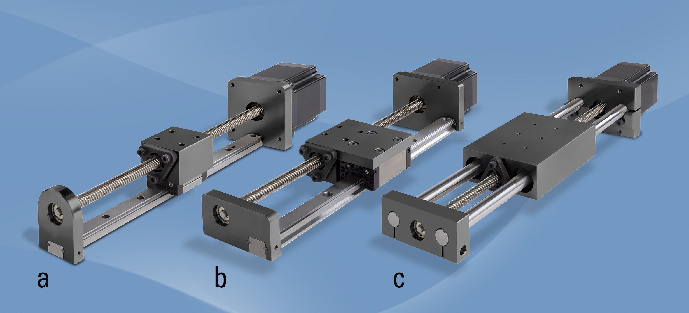
Small systems like these are often available in one of three standard configurations. When the application needs a smaller footprint but has vertical space available, the designer might choose an assembly that stacks the lead screw vertically above a profile rail, as shown in Figure 1a. This slim configuration has a smaller footprint than other comparable configurations but is taller and thus requires more overhead space.

Figure 1: Standard compact linear system configurations may include the lead screw mounted vertically above profile rail (a), alongside profile rail (b) or flanked horizontally by round rails (c). Photo courtesy of Thomson Industries, Inc.
Where overhead space is limited, however, designers might arrange the screw and profile bearing horizontally, as shown in Figure 1b. This configuration flattens the configuration but demands a larger footprint.
A third standard popular configuration involves mounting round rails on each side of the lead screw, as shown in Figure 1c. This version can span across gaps without requiring full support along its length. Dual rail configurations, such as the system shown in Figure 1c, can also handle roll moment loads because two evenly spaced rails share the load.
A final example of a flexible design is one that enables its use in dirty environments while providing positioning and movement using ball screws and linear bearings. The enclosed design provides greater application opportunity while keeping the design in a standard product family, as seen in Figure 2.

Figure 2: Positioning slides utilizing screw support technology and a plastic cover strip system allows operation in dirty environments, keeping the internal system components fully protected while reducing friction to a minimum. Image courtesy of Thomson Industries, Inc.
Fine-tuning
These configuration examples represent a range of possibilities that are available using just standard components. They are typically offered in a wide set of standard sizes and have served most purposes. As modern industrial processes evolve, however, the demand for more complex configurations grows.
Despite the complexity of future manufacturing, most emerging applications will not require total customization. As manufacturers continue to broaden but standardize their product offerings, designers will be able to create a solution using off-the-shelf modules that require minor adaptations. Systems might need shorter or wider support blocks, relocated mounting holes, different bolt patterns, re-orientation of the guide rails to the lead screw, modified stroke lengths or resizing of the motor to accommodate load changes. These minor modifications fall within the existing manufacturing process limitations for the product. Manufacturers are beginning to incorporate these minor modifications into their process to expedite delivery times, while providing flexibility in their offerings.
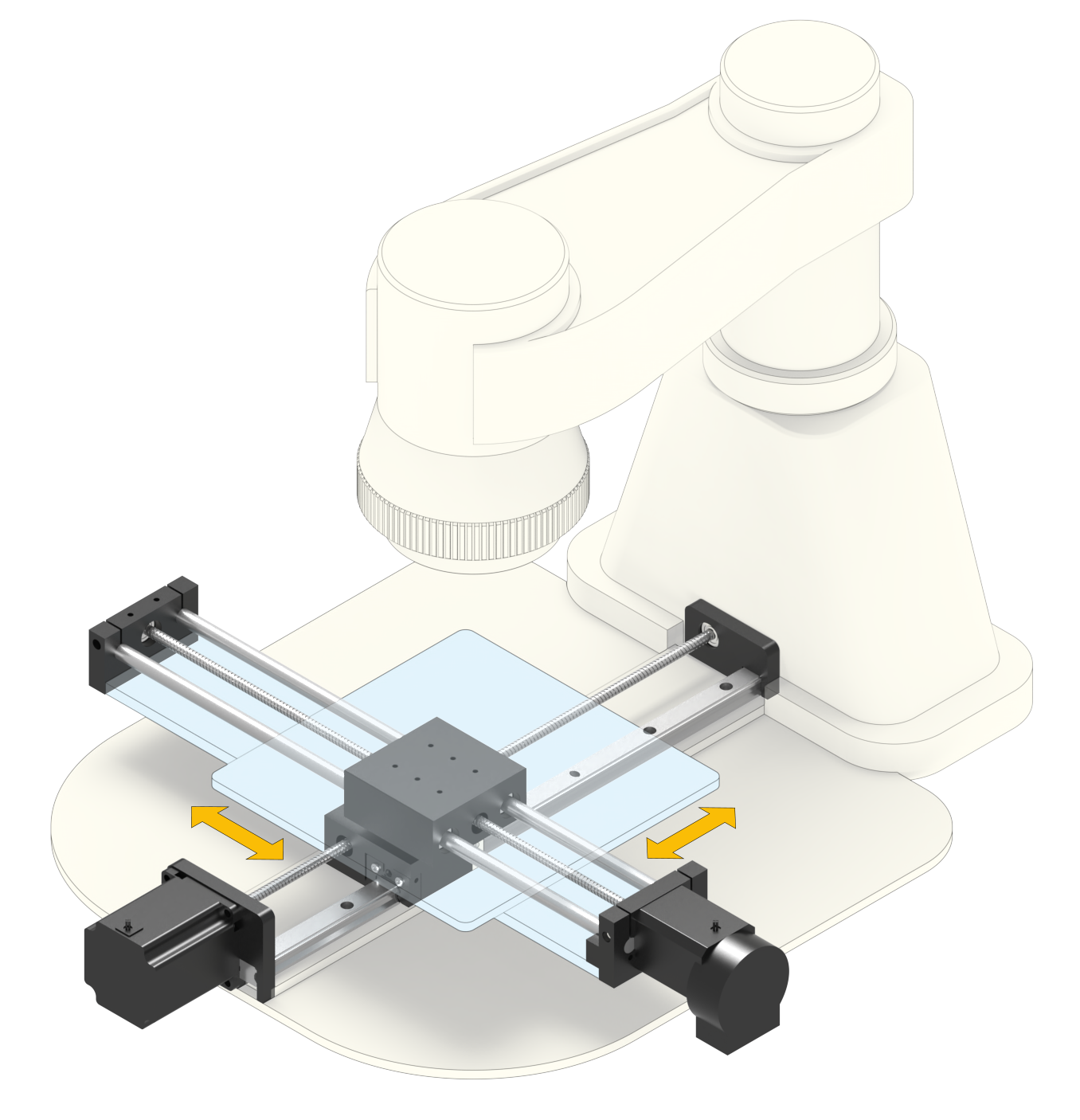
Suppose that the designer concerned with moment load handling chose the configuration with two round rails flanking the lead screw (Figure 1c). The application requirements changed during the design process and then required a higher moment load capacity. Starting with off-the-shelf round rails, lead screws and nuts, the engineer can adapt and accommodate the change. This may be achieved by widening the mount of the existing product or upsizing the bearings to maintain a specific envelope. Because mounting blocks are machined individually, changing support block designs can be done with very little added expense and is a result of using standard product. XY assemblies are yet another type of application that often benefit from adapting standard modules. (Figure 3) Like the previous examples, these units might require redrilling mounting holes, or modifying mounting surfaces for customized gantries to accommodate cable management, limit switches or pneumatic hoses/accessories. These types of considerations are usually very specific to the application. But even then, much of the adaptation is done by using standard mounting blocks.

Figure 3: XY stages can usually be built with standard compact linear components, but gantries and other peripheral components may require customization. Image courtesy of Thomson Industries, Inc.
Critical success factors
Targeting customization to only specific components can have tremendous value in cost-optimizing your motion control system for confined space operation. The success of this approach, however, depends on three things: the breadth of the vendor’s product line, the expertise of the design team comprised of the end user, distributor and vendor, and the extent to which modern engineering collaboration tools can be leveraged. These could be as simple as drawings, sizing tools or even simulation software.
The product line breadth is important because it compresses the supply chain, eliminating the cost and time needed to locate and bring in outsourced components. It also means that the vendor will have more capability to mass produce the product efficiently.
The design team’s expertise is important because they may bring experience with similar adaptations or additional insight of a manufacturer’s abilities within a product line. The combined application knowledge of the end user, distributor and manufacturer will always offer more information and views on how to tackle a difficult application.
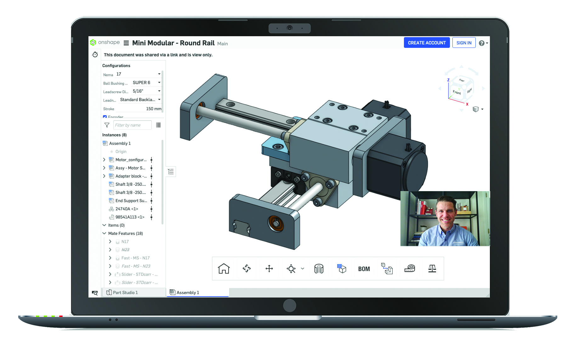
Lastly, the use of modern engineering collaboration tools is valuable because they enable real-time collaboration around the customer’s specific problem, which shortens the time between customization and production. (Figure 4)

Figure 4: Collaboration tools such as virtual design consultations allow customers to work side-by-side with an application engineer to optimize their solution and review CAD models during or after their session. Image courtesy of Thomson Industries, Inc.
Moving into the future
If the automation industry trend-spotters are right, we are on the verge of Industry 5.0, where humans and machines interact more effectively to leverage the unique benefits of each. As part of expanded cyber-physical interaction or the extended internet of things (EIoT), there will be more axes of motion to benefit from automation. Standard linear motion technology will continue to drive the bulk of applications in this space, and targeted customization with a foundation of standard products will make the transition smooth and cost effective.
[SIDEBAR]
Linear System Design Tips
1. Consider the environmental conditions under which the system will operate, including temperatures, dust and dirt levels, chemical exposure, washdown processes, vibration and shock load, and radiation. Fully enclosed units that use a cover strip may be required for dirty and/or wet environments, but in clean factory environments, open designs may provide cost savings and enhanced design flexibility. In extremely dusty environments, fully enclosed units can be equipped with a positive air pressure system to purge any particles that may get through the cover strip.
2. When defining the direction and magnitude of your load, the system orientation can be important. With a horizontal orientation, the drive load is equal to the payload weight times the frictional coefficient, while with a vertical orientation, the drive load is equal to the weight. For vertical applications, know that the mechanics alone may not be enough to hold the load when it is stationary, and an external brake may be needed. This could extend the overall length of a unit.
3. For applications that require accurate positioning, preloaded ball screws or high-precision lead screws can be used, and the mounting surfaces of the rails can be machined.
4. Lead screw drives, which are used in low to medium duty cycle positioning applications, operate at low noise levels and provide excellent repeatability of 0.005 mm.
5. Purchasing a configured linear motion system can typically reduce engineering time and assembly cost by 90% or more, w


