


Electromechanical rodless linear actuators can offer better load handling in smaller spaces than rod-style actuators, but realising those benefits requires careful attention at the specification level. Whether you are replacing a failed actuator, looking for better performance or building a new application from the ground up, success depends on how precisely you specify application requirements.
Unlike rod actuators, in which a piston extends unsupported beyond the actuator housing, rodless actuators use a carriage (also known as cart or truck) on which a thrusting mechanism moves a load back and forth on a track. Getting the optimal efficiency, reliability and overall performance requires careful balancing of numerous variables.
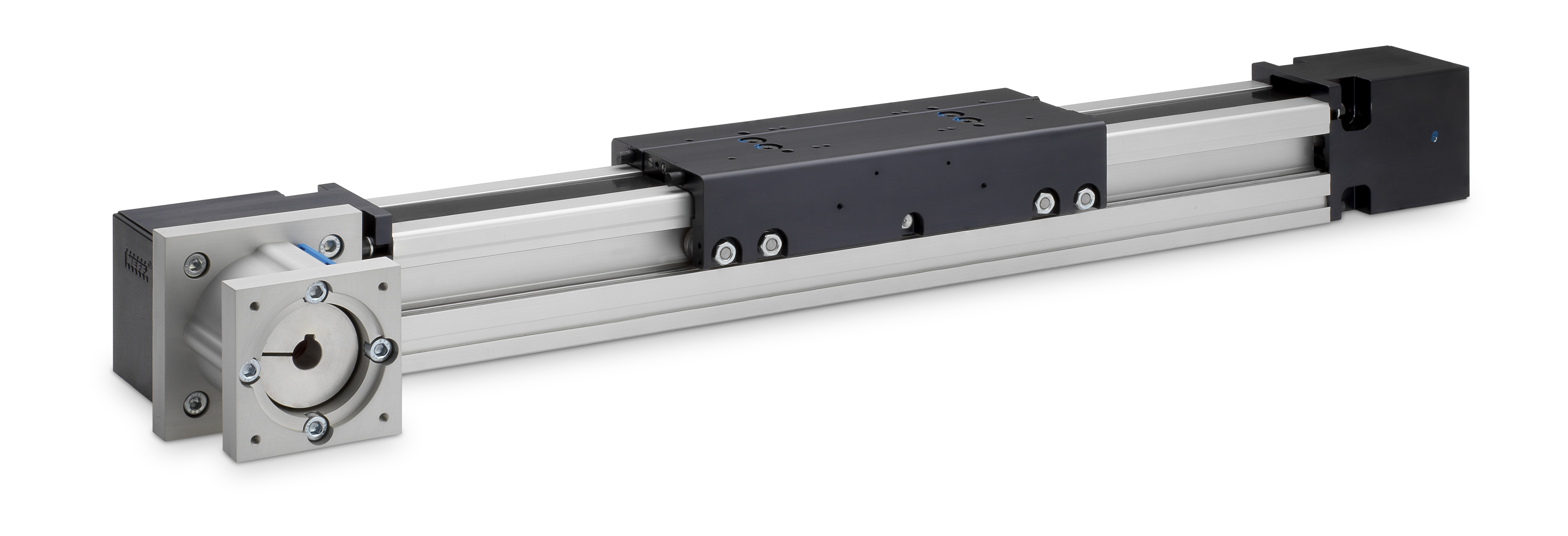
Rodless actuators are designed for advanced precision benefits and offer a wide selection of options depending on the system designers’ needs (image courtesy of Thomson Industries, Inc.).
Whether interchanging actuators or specifying new ones, basic principles are similar. Rodless actuators are distinguished from each other primarily on the basis of the lengths, widths and heights of their profiles. Common dimensions include 40 x 40mm up to 120 X 120mm. Within that range, realising the potential benefits requires a careful analysis of required stroke length, maximum speed, dynamic carriage load and bearing requirements. Through this analysis, motor selection, mounting fixtures and required control adjustments can be considered. Key components for selection are the thrust mechanisms and guide systems, supplemented by determination of the service factor, motors, sensors and other accessories.
Selecting thrust mechanisms
Thrust mechanisms commonly deployed in rodless actuators are lead screws, ball screws or timing belts.
Lead screws: Also, known as acme screws or trapezoidal screws, these deliver rigidity and high thrust in a small package. The action between the screw and nut is sliding, has a high friction factor and is inefficient, although it sometimes can be beneficial in that it provides a self-locking tendency when the system is at rest. Increasing clearance caused by wear between the screw and nut will determine the useable life of the actuator. Some vendors, however, now outfit actuators with plastic, self-lubricating nuts, which extends their lives.
The pressure velocity (PV) limit is another factor impacting lead screw load and speed ratings. Pressure equates to thrust, so as the thrust goes up, the speed goes down and vice versa. Lead screw actuators can have strokes as long as three meters but are most often found in smaller, lighter-duty applications.
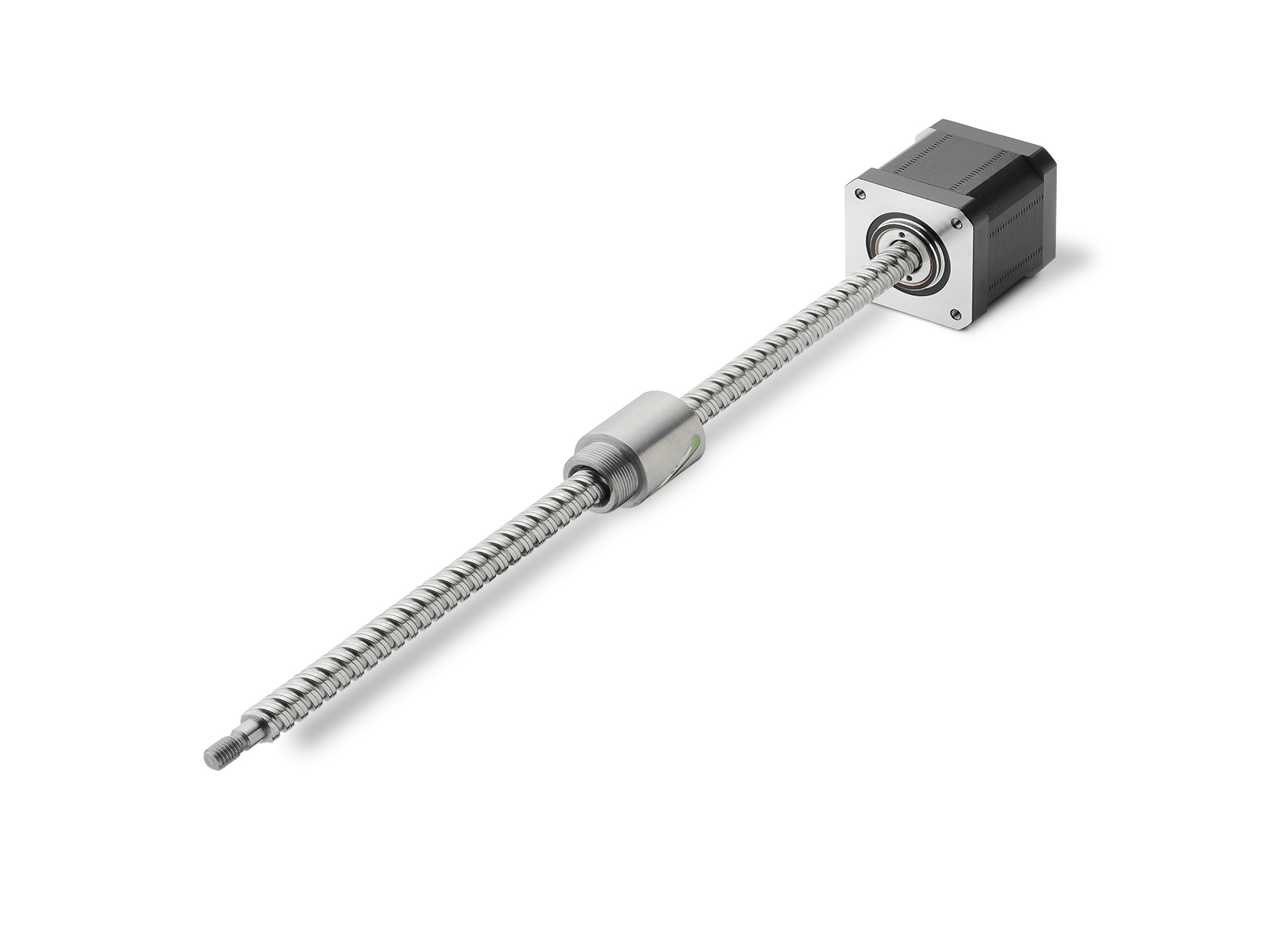
A motorised lead screw offers increased torque density and improved operating battery life (image courtesy of Thomson Industries, Inc.).
Ball screws: Ball screw actuators are much more robust and fit better in most industrial applications. For example, a ball screw actuator built on a 120 mm extrusion with a 32 mm diameter and a 20 mm lead precision rolled ball screw would have a thrust capacity of 12,000 N and a maximum velocity of one meter per second with 3,000-rpm input. The same actuator and screw diameter deployed with a 40 mm lead, however, would have a velocity of two meters per second and a thrust capacity of 8,000 N. A typical precision rolled ball screw and ball nut could have a position repeatability ranging from ±.01 mm or less.
Rolled ball screw actuators offer a cost-efficient solution for applications requiring strokes of up to three meters. Ball screw actuators can be selected to optimise power density or small size per thrust. The L10 life is predictable because the ball nut is essentially a ball bearing and uses the same ISO calculation. The length of the screw affects the load rating, due to the buckling limit, and generally the speed rating, due to excessive vibration. Some vendors, however, add screw supports that enable input speed up to as much as 3000 rpm, independent of the screw length.
Two other factors that contribute to the load capacity of a ball screw driven rodless actuator are the ball nut arrangement and the carriage length. A longer ball nut or a double ball nut will increase the thrust capacity, while a longer carriage increases the length or spacing of the bearings and increases the moment capacity. Thomson Industries, for example, offers a ball screw, ball bearing guide actuator with a single or double ball nut. The single nut version of its 80mm x 80mm profile unit has a 200-mm-long carriage, a thrust capacity (FX) of 3,500 N and a pitch moment (My) of 180 Nm. The corresponding double nut version has a 280-mm-long carriage, a thrust capacity (FX) of 5,000 N, and a pitch moment (My) of 300 Nm. The double nut is also more rigid and will have a slightly better repeatability and reduced axial play.
Timing belt thrust mechanisms: These actuators are also robust and fit in most industrial applications. Actuators equipped with high tensile strength timing belts can handle large thrust loads, velocities up to 10 m/s and are almost unlimited in length. For applications requiring strokes of more than three meters, they are more cost effective than rolled ball screw actuators. Timing belt actuators are also clean and contaminant resistant. A timing belt mechanism built on the same 120 mm extrusion as a ball screw would have a thrust capacity of 5,000 N with a 2,308 rpm input and velocity of 10 m/s. The belt travel would be 260 mm per pulley revolution with ±.05 mm position repeatability.
Selecting guide systems
Careful specification of the guide systems that support the carriage and all the forces acting on the attached load as it travels is another critical success factor for rodless actuators. These can be specified with plain bearings, ball bearings, cam followers and/or wheels.
Plain bearings: These will have a higher friction factor than the rest, however, they often do not require lubrication and can survive in contaminated or wet environments. Plain bearings also dampen vibration, run quietly and can tolerate short strokes at high cycles. Plain bearings or slide guides run either along the aluminum extrusion or are on a set of rails formed into the extrusion. They can be made of different materials such as hardened steel, stainless steel or anodised aluminum. The plain bushings could also be made of a number of materials, including polymer material, PTFE and many low-friction plastics.
Ball bearing guides: Consisting of recirculating ball bushings attached to the carriage, these run on hardened steel rails, which are using bolted onto the extrusion or steel inserts. There may be a single profile rail for a more compact actuator or a stronger double rail. Ball guides offer high accuracy, high load ratings and medium speeds.
Wheels and cam followers: Simple and economical, these also run on hardened steel rails which are formed into the extrusion, and offer high load capacity, high speeds and medium accuracy. The sealed ball bearings are maintenance free and contaminant resistant.
Service factor
The service factor is a key variable in selecting a rodless actuator. After calculating the load, determine the service factor from vendor-supplied load rating in the FX, FY, and FZ directions. The thrust mechanism handles the X component force; the Z component force is the weight sitting on the carriage plus any force perpendicular to the top of the carriage; and the Y component force acts perpendicular to the side of the carriage. From these moment loads (My, Mx, and Mz) pitch, roll and yaw can be solved.
In a typical cycle, a linear actuator accelerates, runs and decelerates at least once during the travel in each direction. There could, however, be many stops along the length of travel. The moment loads is the force needed to accelerate the driven component and its position relative to the carriage. Even driven components with their own guide systems will still have pitch and yaw moments acting on the carriage.
Motor options
Servo or stepper motors are typically the prime drivers for rodless actuators. Standard AC and DC motors are also used to drive linear actuators, but their duty cycle is limited to the number of starts per hour the motor can handle. Actuator manufacturers typically offer metric and NEMA motor brackets with or without a motor attached. The torque and RPM required will ultimately determine the motor’s size.
Automating the selection
Linear MOTIONEERING® is an online tool that Thomson offers for the sizing and selection of their linear components, including actuators. Users input information such as environment, repeatability, stroke, move distance, move time, duty cycle, orientation, loads and forces, resulting in a customised selection of actuator solutions.

Rodless actuators are highly used in packaging application machines as they provide efficient and precise load handling solutions (image courtesy of Thomson Industries, Inc.).
For example, a designer is working on a packaging machine that requires a horizontal axis with a stroke length of 1,500 mm to pick and place products into cartons. By entering the stroke length details, along with other application parameters such as mass connected to the moving carriage, any offset distance from the carriage to the center of the mass, and cycle requirements, they will be presented with the most ideal, economical solutions.
Once the basic actuator is selected, the tool helps accessorise with sensors, mounting brackets and a motor attachment kit, including mounting screws and couplings. A complete model code and pricing are also provided. And finally, it calculates a complete motion profile, including continuous and peak torques, maximum velocities, and expected life.
The right mix
System designers considering rodless linear actuators have many options from which to choose. Almost any combination of lead screw, ball screw or timing belt, implemented with slide guides, ball bearing guides or wheel guides could provide the right solution. Other factors such as cost, availability, environment and service factor will eventually come into play. It is critical to enter the specification task with a thorough understanding of the intended application and objectives across the component lifecycle.